How to use equations in SOLIDWORKS (basics + advanced)

Equations are underappreciated.
You can make one feature adapt to changes in another. You can make your model smarter.
So let’s dive right in.
Within this post, you’ll find…
- How to create equations
- Where can I use equations?
- Can I use custom property values in equations?
- How to use dimensions in an equation
- How to use the equations viewer
- Available mathematical functions
- If-then-else
- Suppress and unsuppress features and relations
- Configurations
- Store a measurement as an equation
- Export equations to a text file (+how to import)
- Create equations with the API
- Equation driven curves
- Quick tips
A model that is driven by equations
1. How to create equations
You can create an equation all around SOLIDWORKS.
It works in sketch mode and also while entering the extruding thickness, in the equations viewer…..
Just start a dimension with an equals (=) sign, add a formula and press enter. This is now an equation.
If you type an equation (like 3*6) without the equals sign, then this does not create an equation. SOLIDWORKS just calculates the value once.
You can also create an equation within the equations viewer.
2. Where can I use equations?
You can use equations for all kinds of features: extrudes, linear patterns, fillets.
But not everywhere.
Check out this page by SOLIDWORKS with the complete list.
3. Can I use custom property values in equations?
This section used to say “No”.
I don’t know what changed, but you actually can.
Check out this section in our blog post on custom properties.
4. How to use dimensions in an equation
When you create or edit an equation, you can click any dimension to add it to your equation.
Start with an equals sign. Keep the dimension box open.
Now to add a dimension from a feature, double click the feature to show all dimensions, then click the dimension to use it in your equation.
If you click a dimension once and an edit textbox pops up, you need to turn off Instant3D first.
5. How to use the equations viewer
You can access the equations viewer in the following three ways:
- Right-click the equations folder in the feature tree > Manage Equations
- Go to Tools > Equations
- Tools toolbar > click the Equations icon
Help, I don’t see the equations folder in the feature tree
By default, the equations folder in the feature tree shows up after you add the first equation.
When the equations folder isn’t visible, you can show it by right-clicking in the empty space in the feature tree and selecting Hide/Show Tree Items.
There you can set the visibility to Show, Hide or Automatic.

Understanding the equations viewer
When you open the equations menu/viewer, you will see a window like this one:

So there are a lot of buttons and options here. These are the visible ones:
- Top row: four different ways of viewing the equations, a search/filter bar, undo/redo and the configuration selector
- Center: main window with Global Variables, Features and Equations
- Bottom row: rebuild and other settings, linking the equations to a text file
- Right: OK, cancel and import/export options
These controls are usually hidden though:
- Right-click anywhere in the row to delete an equation
- Starting from SW 2017, right-click the row to disable an equation. You can now find it in the fourth tab, marked as Disabled.
- Click the value column to show a pop-up menu. It shows you variables that you can use, mathematical functions and model properties.
- Click the value column to show the configurations settings. Here you can vary the equation across configurations.
- If the syntax of your equation is correct, a green arrow appears.
Four ways of viewing all equations
The goal of the four views isn’t immediately clear, at least not to me. These are their functions:
- Equation View: show all global variables and equations
- Sketch Equation View: only shows the global variables and equations that are used in sketches
- Dimension View: show all global variables, equations and all model dimensions
- Ordered View: global variables and equations, shown in the order that they are solved when they depend on each other
Three groups of variables
I’ll re-post the equations window so you can clearly see the three groups of variables:
- Global Variables
- Features
- Equations
First group: Global variables
A global variable is a named variable that you can use it throughout the part/assembly.
All you have to do is type in a name (with or without double quotes, SOLIDWORKS adds them when you don’t) and a value or equation.
You can use other variable names when you enter them between double quotes: =”height” * 12 is a working equation when you define the variable height as well.
You can use the global variables:
- when you enter a sketch or feature dimension
- while creating an equation
- while creating a custom property
- when you create a weldment
Second group: Features
This group lets you determine the suppression state of features, depending on the outcome of equations.
To enter a value in the first column:
- Click in an empty cell
- Then click a feature in the feature tree
Enter a text like =”unsuppressed” or =if(“var6″>3,”suppressed”,”unsuppressed”) in the second column.
Third group: Equations
I would rather call this group Dimensions than Equations. You can enter a new item by selecting a dimension in a sketch. You can then create an equation to calculate the value for this dimension.
If you created an equation in a dimension dialog box, the equation will also show up here. The same holds for linked dimensions.
Ditch the Toolbox, once and for all
Start using the fastener library that actually follows the standards
- No more mate errors
- Made for speed
- No yearly license fees
6. Available mathematical functions
There’s a limited set of mathematical functions that you can use in your equations.
Once you start entering a value, a popup shows you the possibilities:
- Trigonometric functions like sin, cos, tan, arctan and cosec
- Square root: sqr
- Logarithmic functions: log and exp
- Value properties : integer (int), absolute value (abs) and sign (sgn)
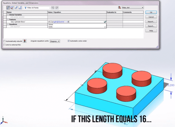
7. If, then, else
The final entry in the list of mathematical functions is the IF (or IFF) function from VBA. When you enter an IF statement, SOLIDWORKS will usually replace it with an IFF.
The difference is explained here, but what it comes down to is that every option is evaluated and one of the results is returned. So dividing by zero will result in an error, even when that side of the if-statement isn’t applicable.
You can create functions like:
= if ( “variable3” > 100 , 10 , 20 )
This will make the variable in front of the equal sign equal to 10 if variable3 is greater than 100. If not, it will be set to 20.
Creating nested functions is also possible:
= if ( “var3” > 100 , if ( “var3” > 200 , 30 , 20 ) , 10 )
You can only use numbers
I have received multiple questions in the chat, asking me if you can use strings (text) in your equations.
This is not possible. You can only use numbers in the equations and the answer also has to be a number.
8. Suppress and unsuppress features and relations
A very basic version of suppressing features has been in SOLIDWORKS for years.
However, you could only suppress a feature by creating an equation like “Feature 1″ =”suppressed”. The help files said it should be used for debugging your equations only.
Since 2014 you can really use the suppression state in an if, then, else function.
This video by TriMech Solutions shows it very well. Just view it in full-screen mode (and skip to 1 minute 20 seconds for the equations).

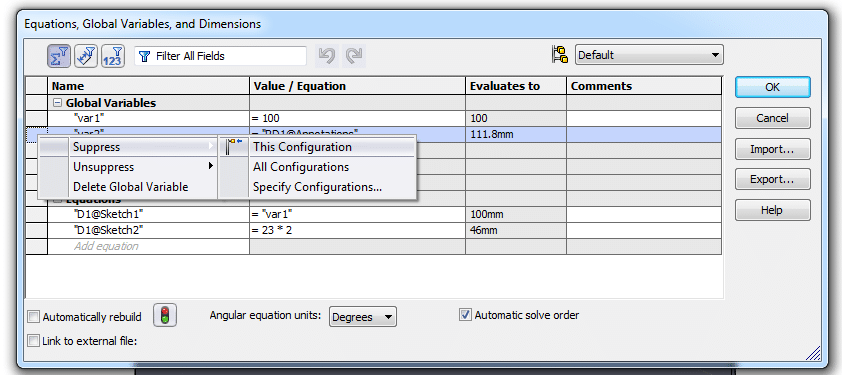
9. Configurations
Suppressing equations
Older version of SOLIDWORKS (think 2013 and before) would let you suppress an equation and set its suppression state per configuration.
Current SOLIDWORKS versions do not let you suppress an equation anymore, but older versions would.
A suppressed equation would be hidden or grayed out.
Suppressing equations in old SOLIDWORKS version
Vary the equation between configurations
You can now only configure the equation itself, as shown in this video by GoEngineer. Skip to 2:00 if you’re in a hurry.

10. Store a measurement as an equation
This is a strange one. To add a measurement:
- Create a new variable by entering a name
- Click the value column
- Enter the equals sign, then click Measure in the popup menu. This does not work in sketch mode.
- Click an edge or other model item, then drag to create a dimension, or click an existing dimension
You have now added a driven dimension to your model. The dimension doesn’t show up in a sketch or feature. It’s called an annotation, but it won’t be listed as such.

11. Export equations to a text file (+how to import)
The two buttons labeled Import and Export should speak for themselves.
You can create a text file by exporting your equations and you can reuse them using the import function.
In addition, if you want multiple parts to use the same text file with equations, you check the box labeled “Link to external file”.
This will then keep the equations in sync. Because of the synchronization, you will have to edit the text file to edit the equations.
12. Create equations with the API
First of all, to add and edit equations using the API, you need to create an Equation Manager.
Adding an equation can be done using either Add2 (faster, no configuration support) or Add3 (newer, using configs).
Note that to use double quotes inside a string in VBA, you need to add them twice.
Open a part (with sketches called Sketch1 and Sketch2) and run this simple macro to add two equations:
1 2 3 4 5 6 7 8 9 10 11 12 13 14 15 16 17 18 19 20 21 22 23 | Option Explicit Sub Main() Dim swApp As SldWorks.SldWorks Dim swModel As ModelDoc2 Dim EqMan As EquationMgr Dim index As Long, RetVal As Long Dim equation As String Dim i As Integer Set swApp = Application.SldWorks Set swModel = swApp.ActiveDoc Set EqMan = swModel.GetEquationMgr equation = """D1@Sketch2"" = 3*6" index = -1 'Using -1 will add it to the end of the list EqMan.Add2 index, equation, True Debug.Print EqMan.GetCount i = 6 EqMan.Add2 i, ("""D1@Sketch1"" = (IIf(""var7"">20, 25, 20))+3"), False End Sub |
13. Equation driven curves
This is a feature you can include in all sketches, so 2D and 3D.
You can add a curve to a 2D sketch using Tools > Sketch Entities > Equation Drive Curve or by expanding the curve icon in the sketch toolbar.
This menu isn’t self-explanatory though:

Adding an equation drive curve
Fortunately, the official help page will give you a flying start.
Explicit
As it turns out, you can use X here to calculate Y and enter the start and end value for X. They draw half a circle by entering sqrt( 4 – x ^ 2) in the Y-box, -2 for the start value of x and 2 for the end value.
As a result, creating a straight line can be done by entering a linear function like 2*x+10.
Parametric
If you select the parametric option, you can define formulas for X and Y separately. That means you can draw all kinds of funky lines.
The great thing about these equation driven curves is that you can drag them after you define them. When you unlock the endpoints, you can even drag and redefine those.
Once you enter a 3D sketch you will get the option of adding a 3D curve using the menu shown below.

Creating a curve in a 3D sketch, these settings will result in a spiral
In conclusion: curves in 3D can be used to create spirals, springs, staircases and zig-zag lines. So just play with them and see what happens.
Soon you will find a good use for a 3D curve. I guess.
14. Quick tips: using units, design tables, BOM values
- You can use all kinds of units, you can even combine them. Entering =3 inch + 6 mm should work perfectly. It looks horrible though…
- Entering an equation in a Design Table can be done as well. Just make sure you start the cell value with an apostrophe so Excel treats it as a string. Example: ‘=”D6@Sketch4″*3
- You can add a calculated value column to a Bill Of Materials (Javelin howto)
15. Smart lego blocks, here we come!
So that’s everything I know about equations in SOLIDWORKS.
This post has become quite a read, because of all the options that SOLIDWORKS has to offer. Well done if you read everything up to this point!
So now it’s your turn to draw your own smart Lego blocks. Just don’t try to 3D print them, because you’ll only learn that they need to be damn accurate.
Want to learn even more? Then check out our articles on balloons and InPlace mates.