How to create Routing components

In this post, we’ll show you how to prepare models so you can use them as Routing components.
SOLIDWORKS Routing has many hidden tricks, features and requirements.
Our goal is to collect all of them in this post.
In this post, you’ll find
- What is SOLIDWORKS Routing?
- How to create pipes for your routing library
- How to create flanges and tees for your Routing library
- What are (Assembly) Connection Points?
- What are (Assembly) Route Points?
- Rules for reference axes in Routing
- Rules for Mate References in Routing components
- Rules for configurations
- Rules for design tables
- Custom properties in Routing Components
This post will be a constant work-in-progress, so please let us know if you have something to add, if it lacks crucial info or if it contains a mistake.
1. What is SOLIDWORKS Routing?
For more general information about the SOLIDWORKS Routing add-in, check out our article How to create a Routing library from scratch.
This article started out as a section in the routing library post, but it quickly became large enough to warrant its own post.
2. How to create pipes for your routing library
Pipes are incredibly easy, compared to flanges and tees. The rules are documented and clear.
But these rules are very strict.
- The default file from SOLIDWORKS is simply called pipe.sldprt but it can have any name.
- You usually need only one part file
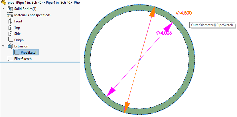
- There is a single extrude. The sketch has two concentric circles.
- Extrude name: Extrusion
- Extrusion length name: Length@Extrusion
- Extrusion direction: positive Z-axis
- Sketch name: PipeSketch
- Sketch plane: Front plane
- Inner diameter dimension name: InnerDiameter@PipeSketch
- Outer diameter dimension name: OuterDiameter@PipeSketch
- There is a second sketch that contains one circle.
- Sketch name: FilterSketch
- Diameter dimension name: NominalDiameter@FilterSketch
- SOLIDWORKS uses the nominal diameter to link a pipe to a CPoint in a flange. So the diameter and schedule should match between the pipe and the flange.
- The FilterSketch circle diameter dimension is called NominalDiameter. The name is critical.
- This nominal pipe diameter needs to match when you connect a pipe to a flange.
- A design table with at least these seven columns:
- The configuration name. Needs to be column A.
- $PRP@SWbompartno: The custom property that is used in a BOM.
- $PRP@Pipe Identifier: Custom property with a unique identifier
- Example values “2 inch, Schedule 40” and “DN 100 PN 16”
- $PRP@Specification: Custom property with schedule or PN designation.
- Needs to match Specification@Cpoint
- NominalDiameter@FilterSketch
- OuterDiameter@PipeSketch
- InnerDiameter@PipeSketch
- The values in the first three columns are usually identical
- These custom properties are optional for your design table:
- $PRP@Schedule Number: The property SOLIDWORKS uses in the database for Schedule. Seems not to be used anywhere.
- $PRP@Class: The property SOLIDWORKS uses in the database for Class. Seems not to be used anywhere.

You need to follow the rules above to the letter
- All sketch and dimension names are case sensitive.
- This may be the only place within SOLIDWORKS where this is explicitly the case.
- Custom property names should not be case sensitive.

More info in the official SOLIDWORKS help:
Our other article has a section on how to use the new pipe file by adding it to the database.
3. How to create flanges and tees for your Routing library
You can use any part or assembly as routing components in a routing assembly.
But you need to add a few features to the model first. Click them to go to the correct section.
- A Connection Point at each open end
- One Route Point
- Reference axes
- Mate references (optional)
- Configurations
- A design table (recommended)
- Custom properties
You can do this in two ways:
- When you know what you’re doing, you can add each feature manually
- If not, use the built-in tool to help you with this:
- Open the file you want to prepare
- Click Tools > Routing > Routing Tools > Routing Library Manager
- Go to the Routing Component Wizard tab
- The steps are pretty straightforward, although not always immediately clear. Your goal is to get rid of all red text, so only green text remains.
- Innova Systems wrote a nice blog post on this wizard, so we don’t need to go into detail for each step here.

4. What are (Assembly) Connection Points?
A Connection Point or CPoint defines where the pipe, tubing or cable starts or ends.
It is a feature in the feature tree. You can only edit this feature when the Routing add-in is enabled.
Connection points are for parts, Assembly Connection Points are for assemblies.
When you add a flange to an existing piece of pipe, the flange connects at the connection point. If the diameter and schedule match.
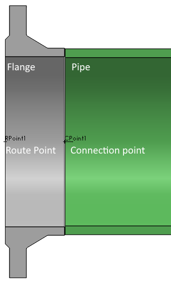
It has a position and a pipe direction. You can see where SOLIDWORKS adds the connection point to a welding neck flange in the image below, exactly at the connecting face between pipe and flange.
A fitting needs a connection point for every port, so a flange needs one CPoint and a tee needs three CPoints.
A unique thing I found is that SOLIDWORKS always names the first point CPoint1, even if you deleted one previously. Normally it just increases the count, it never reuses a number.
Very important CPoint parameters
There are a few important properties that you need to set here. For piping, you need to set at least these:
- Diameter: the nominal diameter of the pipe that needs to be attached.
- Needs to match the setting in the pipe part. Note that this value in a CPoint is not linked to any geometry.
- Controlled in a design table with Diameter@CPointN
- Schedule field name: the name of the custom property that you use to store the schedule.
- The default custom property is called “Specification”. Keep this field empty if you use that or enter any other name.
- Pipe and fitting parts need to have matching schedules.
- In ASME this is usually called Schedule, for Europeans, it is the PN number.
- Schedule value: the value of this custom property.
- Controlled in a design table with Specification@CPointN
- Example values are “Schedule 40” and “PN 10”, without the quotation marks.
You only need the Port id if you read in P&ID files automatically.

More info on CPoint properties
Forum topic on schedules and the importance of the CPoint properties.
5. What are (Assembly) Route Points?
A Route Point or RPoint defines the position where you add the component to the existing 3D sketch.
Just like the CPoint, it’s a feature in the feature tree. You can only edit this feature when the Routing add-in is enabled.
Route points are for parts, Assembly Route Points are for assemblies.
It is a much simpler feature than the CPoint and has only one parameter, its position.
For a welding neck flange, like in the image below, it makes sense to have the route point at the connecting face.
When you add the flange to a route, the route will become a little longer because the flange snaps in place at the connection point.
You need one RPoint per routing component. Only excentric reducers need zero.
For a flange, this marks the end of the pipe.
For a tee or elbow, the route point marks the intersection of the ports.
More info on CPoints and RPoints.
6. Rules for reference axes in Routing
For flanges at least, you need to create two reference axes:
- A reference axis named “Axis of Rotation”
- A reference axis named “Vertical”
SolidWorks looks for these names and the names are probably case sensitive. We could not find clear proof, the best we could find is this help article.

7. Rules for Mate References in Routing components
What are mate references?
Mate references are a great way to make parts snap in place when you drag them into an assembly. This is a good introduction video and it’s only 4 minutes long.
You say which edges and faces are important, define the alignment and then give the mate reference a name.
If you define mate references on one part like we do on our fasteners, you can easily drag parts into a hole in another part and SOLIDWORKS will add one or two mates.
When you define mate references on two parts that should always go together, you need to give the mate references the same name. You also need to define the faces in the same order.
Mate references for Routing
Mate references are not mandatory for routing parts, but they are very useful.
When you create a new route (and thus a new subassembly) by dragging in a flange, the flange will snap to an existing flange. SOLIDWORKS then adds a few mates, instead of making the new subassembly fixed.
We have found two mate reference types in the default library. You should use these names to make all parts work together.
- A mate reference on the connecting face (coincident, anti-aligned) and the center hole face (concentric). Name it “Default“.
- A mate reference on the edge between the connecting face and the center hole. Name it “Edge“

8. Rules for configurations
Multiple configurations are pretty much required for routing components to work well.
Matching pipes with other components
When you add a flange (or any other component) to an assembly, SOLIDWORKS searches through all configurations within the new file.
It then tries to match:
- The diameter of the CPoint to the NominalDiameter of the pipe
- The schedule of the CPoint to the Specification custom property of the pipe.
Configuration names
Configuration names are very important, it seems. According to this forum post, SOLIDWORKS searches the configuration name for sizes and schedules.
I cannot confirm this yet, but this setting in the Route Properties tab hints at such functionality.

9. Rules for the design tables in Routing components
For those of you that don’t know; a design table is an Excel file. The table is stored within a SOLIDWORKS file and contains a row for each configuration in a model.
You can control dimensions, equations, colors and custom properties, you can even suppress features. You can read all about them in the help.
Routing relies heavily on design tables. All routing files that SOLIDWORKS ships with the software have a design table.
Custom properties are controlled via “$PRP@CustomPropertyName”.
You can find the required columns for pipes and flanges in sections above.
10. Custom properties in Routing Components
When you go through the Routing Component Wizard, this cryptic screen is the second to last step.
The menu on the left is called Component Attributes, but these are actually custom properties.
The top section contains configuration-specific custom properties, the bottom section contains custom properties for the entire file.
SOLIDWORKS adds these custom properties to your file when you click Finish, but:
- It does not add the custom property when it already exists
- It does not overwrite existing values
- It only adds those where you entered a value

Custom properties added by the Routing Component Wizard
- PartNo
- SOLIDWORKS likes to use this custom property in a bill of materials.
- More info in the help
- Description
- Very standard custom property for human-readable info about the component
- Comment
- Material
- Manufacturer
- RouteOnDrop
- Whether to create a new route when you drag this component into an assembly.
- Type: text
- Values: “Yes”, “No”, “Ask”
- More info
- SWbompartno
- SOLIDWORKS uses this property in a BOM for the part number.
- SWPipeLength
- SOLIDWORKS uses this property in a BOM for the length of a pipe.
- Component Type
- Is filled in by the Routing Component Wizard. I selected Piping > End Flange, the custom property value became “Flange”.
- Type: text
- IsogenSKey
- Standard abbreviation to describe the component type
- Example for blank flange: FLBL
- Isogen is software that creates isometric views for 3D piping. More info.
- SOLIDWORKS uses this value to create PCF file exports, which can be read by Isogen and other software.
- Only required property for Isogen
- More info on Isogen properties
- List of SKey values
- IsogenBom
- Optional property for Isogen
- SOLIDWORKS uses SWBomPartNo when this property isn’t found
- IsogenDescription
- Optional property for Isogen
- SOLIDWORKS uses SWBomPartNo when this property isn’t found
- IsogenComponentType
- Optional property for Isogen
- IsogenAttribute1, IsogenAttribute2, etc
- Optional property for Isogen
Conclusion
We could not find a complete list of the requirements for routing components.
But now there is one. We were able to get our own flanges working and we wrote all the crucial pieces of information down here.
Also check out our other post on routing: How to create a Routing library from scratch
We hope it was helpful for you as well. Please let us know if you have something to add.