I think SOLIDWORKS drawings are assemblies – and it blew my mind

I found out something about drawings a few days ago.
And I’ve been thinking about it ever since.
It seems that drawings are just assemblies underneath the hood.
It makes a lot of sense when you combine all the hints that we found.
How I found out
For our drawing automation add-in Drew, we work on drawings a lot. We are continuously looking for ways to optimize, streamline and automate the drawing process for our users.
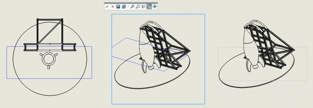
Now I was checking out buttons in SOLIDWORKS that I rarely use, and I found this nifty feature:

This button allows you to actually rotate a drawing view in 3D, like this:

This means that a drawing view is actually just a side view of the 3D model. I had no idea!
Very cool, right? My mind was already blown at this moment.
And then I kept thinking about it.
A proof that drawings are assemblies, in six parts
Part 1: A sheet format is a view
When you program for SOLIDWORKS as we do here at CAD Booster, you can get the first view of the current sheet using the GetFirstView method. But that first view is not an actual view, it’s the sheet.

From the API help
This behavior made no sense to me, until now.
It just means that the sheet is added as the first object to a sheet and the first view is the second object. This gray rectangle can never be deleted. You can delete the sheet format, but the sheet will remain.
You also cannot change the rotation of this view object using code. I tried and failed. I would have loved to show you a rotated sheet format, but SOLIDWORKS prevents changing the angle apparently.
Part 2: Each drawing sheet is an assembly configuration
I am still not 100% sure about this one, but these are my reasons for thinking that a sheet is actually a configuration:
- You can only view one sheet at a time.
- You can open a drawing while only loading one or more sheets. Just like you can selectively open an assembly configuration.
- You cannot suppress a drawing view. (You can hide a view though. I did not know that yet.)
So my conclusion is that SOLIDWORKS adds a component to the drawing/assembly for each view. It then suppresses all views that are not on the current sheet and hides them in the feature tree.
Part 3: The naming of model instances is the same as an assembly
For this one, I created a drawing with two sheets and a number of views. Notice how the view models are numbered with <number>, exactly how SOLIDWORKS names identical components in an assembly.

Feature tree for a drawing
You see the same naming pattern when you hide a component (left) or a body (right) using a right-click on a drawing view, then clicking Properties.


Part 4: Component names have one extra level in views
Each assembly component has a unique name. In a normal assembly, a component name is for example Beam<1> (or Beam-1 in the API). If the component is within a subassembly, the subassembly name is added: SubAssy<1>/Beam<1>.
Yet when you get the components in a drawing view, another layer is added! The same component suddenly becomes MainAssembly<1>/SubAssy<1>/Beam<1> for the first view and MainAssembly<2>/etc for the next view.
So that means SOLIDWORKS adds the main assembly to the drawing every time you add a view.
Part 5: You can load drawings in lightweight mode
Drawings and assemblies are the only model types that can be loaded in lightweight mode. You cannot do this for parts.
When you open a model in lightweight mode, SOLIDWORKS only loads the data it needs. This makes loading large files faster. You can then selectively load extra data for certain models.
Part 6: You create a drawing sketch in 3D, not in 2D
I had a hunch that this one might be true, so it was very cool to find proof for it. I wanted to know what would happen if you create a sketch within a drawing view, then rotate that view in 3D.
The image below shows what happened. You add a sketch with a rectangle (left), then rotate it (middle). HA! The sketch actually rotates along with the view.
When you click OK, SolidWorks changes the sketch back to its original orientation (as shown on the right).
The strangest thing is the plane that is used for the sketch. The view is a top view, so I expected it to use the top view of the assembly. But it actually uses the top plane from the first component within that assembly, which makes no sense at all.
Ditch the Toolbox, once and for all
Start using the fastener library that actually follows the standards
- No more mate errors
- Made for speed
- No license fees
What this all means
So when we know that …
- A drawing is an assembly
- A sheet is an assembly configuration
- A view is just an assembly component with a specific rotation
That also means that…
1: Projected views are connected to each other using mates
Try rotating a parent view using the 3D rotation button. SolidWorks will then ask you if the child views should be rotated as well. What it’s basically asking is: “Should I keep the distance mate between origins and the three parallel mates between the planes?”
2: A cropped view uses a cut-extrude
Once again, I am amazed. How can you show only certain parts of an assembly and hide the rest? By throwing in a cut-extrude of course! Just remove everything outside of the sketch contour by enabling Flip side to cut.
This also explains why you get zero-thickness errors when you create a cropped view.
I tried to let SOLIDWORKS prove this to me by creating a cropped view, then trying to rotate it. But then this popup stops me in my tracks.

Damn it. I mean this one:

This does increase the chance that I am right though because rotating the view would show the cut-extrude. It also means that all these views use similar tricks:
- Details views
- Broken views
- Mirrored views (I didn’t even know these existed, more info here)
- Cropped views
- Detached views
Empty views are the exception. It’s just hard to spin the view when there is nothing to spin.
Why this matters to you
First of all, I just really wanted to share this info with you all. I think the information that drawings are actually assemblies is way too cool to keep it for myself. But I also think it has some practical purposes:
You have a better understanding of what SOLIDWORKS does under the hood, so you can handle accordingly. If you are working on a drawing for a slow assembly, you might think twice about adding another broken out section or a cropped view.
It also means that nearly every trick for speeding up assemblies also works for drawings. That is a massive insight!
We already wrote pieces on Assembly Best Practices and How to speed up slow drawings, so I will update those posts accordingly.