A complete overview of matrix transformations in the SOLIDWORKS API
I’ve been struggling with transformations for a few days now.
And I really needed this post. But it didn’t exist.
So I am writing it now.
If you are having trouble too, this post is for you.
Within this post, you’ll find…
- Matrices are everywhere in SOLIDWORKS (+what is a matrix)
- Matrix transformations: the basics
- Matrix transformations in SOLIDWORKS
- 9 spaces: model space / view space / sheet space
- Available transformation matrices within SOLIDWORKS
- When do I need which transformation?
- Conclusion: transformations are everywhere
- Useful macros
- Useful forum topics
- How you can help to make this article even better
1. Matrices are everywhere in SOLIDWORKS
What’s a matrix?
If you have no idea what a matrix is, then I might have to disappoint you.
We are not going to talk about Neo today (although you might want to check out this cool behind the scenes video).
We’re talking about these things:
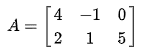
The matrix above has two rows and three columns. A matrix with three rows and one column (called a column vector or column matrix) is used to describe a point in 3D.
It’s basically an arrow from the origin to this point. It has a direction and a length.
![]()
What are transformations?
When you multiply a 3×3 matrix with a 3×1 (3 rows, 1 column) vector, the result is another 3×1 vector with a different direction. This is called a transformation.
The length of the vector stays the same when you only change the orientation.
How matrices are used in SOLIDWORKS
Everything SOLIDWORKS does uses matrices:
- Every 3D point has three coordinates
- Each sketch plane uses its own coordinate system. Check out the coordinates systems on the bottom left, in a sketch on the front plane (left) and on the right plane (right). SOLIDWORKS uses transformations to translate between the coordinate system of the part of the coordinate system of the sketch.

- Every mate creates a row and a column in the mate matrix of the assembly. SOLIDWORKS then solves (simplifies) this matrix to find all component positions every time you make a change, drag a component or do a rebuild.
- Components in an assembly have a transformation matrix that determines their orientation.
- A drawing sheet has its origin at the bottom left, but each view is oriented differently. As I wrote before, drawings are basically assemblies, and every drawing view has a transformation as well.
- Every coordinate system that you add has its own transformation matrix.
- Each pattern instance has its own transformation
- I almost forgot the most visible one: when you rotate your model, all you do is update the transformation matrix. Then SOLIDWORKS calculates which points and faces should be made visible.
2. Matrix transformations: the basics
If you already know how matrix multiplication works, you can skip ahead to the next section.
Translate / move
Translating a point is pretty simple to do. Just add two column vectors to get the sum.
You can only sum matrices of the same size. Each element is the sum of the element in the parts, for example 1+4 = 5.

You can visualize summing vectors by stacking two arrows. The sum is the endpoint of the top arrow.
(The image below does not use the same values as the example above by the way)

Rotate in 2D
I can best start explaining rotation matrices in 2D.
To rotate a x,y vector with angle theta, you multiply the vector with a rotation matrix:

Wolfram Alpha is nice enough to also show how you can manually calculate the X and Y values of the rotated point.
To calculate the X value (the first row), multiply each element in the first row of the matrix by the first column of the original point. Then you sum the results.
To calculate Y (the second row), multiply each element in the second row of the matrix with the first row of the vector. Then sum them again.
I also found this example on StackExchange, which nicely visualizes rotating a square:

Rotate in 3D
Rotations around an axis in 3D use the same rotation matrix as in 2D, but with an added row and column.
When you rotate something around the X-axis, the X-value remains the same. That’s why the first entry is one and all other values in that row and column are zero.
You see the same pattern for rotations around Y and Z. Sometimes the sign for the sine is flipped though:

Image source: Wikipedia
When the rotation is in the wrong direction
I have been coming back to this post for help regularly. Yesterday I noticed my 90-degree rotation around Z gave negative values for the sin(theta) values.
It turns out that there is a difference between the matrix to transform a point from X to X’ is different than the matrix to transform the coordinate system R3 to R3′.
So there is no need to be alarmed. Just be aware.
Source: Wolfram Mathworld, equation 3-6
Scale
To scale a point with regards to the origin, all you need to do is multiply each value by the scale.
That’s it!
Or if you want to use a complete matrix to scale equally in all directions:

Doing manual calculations and checks
The nice thing about 2D and 3D transformations is that you can do the calculations manually on paper as well.
But you can also use the awesome site Wolfram Alpha.
3. Matrix transformations in SOLIDWORKS
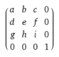
SOLIDWORKS uses 4×4 matrices to define transformations. They call it a MathTransform.
It’s built up out of four sections:

Not used means these values are always zero. The same matrix structure is used in Microsoft .NET Matrix3D for 3D graphics.
Note that SOLIDWORKS names the elements per submatrix. It always uses this custom order, for example when it returns 16 elements as ArrayData:
- 0-8 / a-i / rotation submatrix
- 9-11 / j-l / translation vector
- 12 / m / scaling factor
- 13-15 / n-p / not used
Combined, this matrix creates an affine transformation. This basically means that, when you multiply multiple objects with the same transformation, relations between points remains the same and parallel lines and planes remain parallel.
When you do manual calculations, multiply the vector by the rotation first, then scale the result, then translate that result.
Rotation matrix
To rotate a point (or any other object) around the origin (and keep the scale and the distance to the origin the same), set the values a-i and set the scale to 1:
You can think of each row in these matrices as the direction of an axis. Check out the helpful image that I made below.
The front view uses the standard coordinate system. The top view has the X-axis in the same direction, whereas the right view has the X-axis in Z-direction.
You can also see that the Z-axis in the top view is in the negative Y direction of the front view.

That should make these rotation matrices a little easier to read.
Ditch the Toolbox, once and for all
Start using the fastener library that actually follows the standards
- No more mate errors
- Made for speed
- No yearly license fees
Translation matrix/move
To translate a point in 3D space and keep the orientation and the scale constant, set the rotation matrix to the identity matrix and the scale to 1.
When you multiply a point with this matrix, the point moves j in the x-direction, k in the y-direction and l in the z-direction.
![]()
Scale matrix
To scale a point position with a factor of two, only set the scale factor.

Matrix inverse
You need to use the matrix inverse to create a transformation in the other direction.
For example to go from view to model instead of model to view.
When you already have a MathTransform, you can use Inverse (to receive an object) or IInverse (to receive a MathTransform, which is a little more useful because you don’t have to cast it).
These inverse matrices have some nice properties:
- For a pure rotation matrix, the sign of the rotation submatrix changes (see image below). The top left 1 does not create a rotation because it is on the diagonal, so this value is not inverted.
- For a pure translation matrix, all three values just have a minus sign in front of them
- For a scale matrix, the value is just 1 over the scale. So 2 turns into 0.5

How to combine matrices
Combining a rotation, a translation and a scale is not a problem, just add all of the entries to a single matrix.
But to combine two full matrices, you need to multiply them.
When you multiply two square matrices, the result is a different (composite) square matrix with the same dimensions. You can use MathTransform.Multiply for that within SOLIDWORKS.
According to the SOLIDWORKS support employee I asked for help, the multiplication order does not matter. I still don’t believe this.
One of the first things I learned about matrices is that the multiplication order is of paramount importance. So I decided to test it in SOLIDWORKS.
The matrix multiplication order matters
I created a rotation matrix for a top view (-90 degrees around X) and one for the right view (90 degrees around Y).
Then I multiplied them: top.Multiply(right) and right.Multiply(top). The resulting matrix is not the same.

Rotation for top view * rotation for right view

Rotation for right view * rotation for top view
I have also tested this within SOLIDWORKS with a point. Turns out the order is important after all.
So be careful with this.
The multiplication order SOLIDWORKS uses is from left to right, just as you would read it:
top.Multiply(right) equals doing [top]*[right].
The SOLIDWORKS help does not state this anywhere though.
How to create matrix transformations in the SOLIDWORKS API
Here is a code example on how to create a MathTransform. I prefer to write in C#, but this is in VBA because that is still used by many.
1 2 3 4 5 6 7 8 9 10 11 12 13 14 15 16 17 18 19 20 21 22 23 24 25 26 27 | Option Explicit Sub CreateTransform() Dim swApp As SldWorks.SldWorks Dim mathUtility As mathUtility Dim transform As MathTransform Set swApp = Application.SldWorks Set mathUtility = swApp.GetMathUtility Dim xValue As Double, yValue As Double, zValue As Double Dim transformArray(15) As Double 'Rotation. Note that there are three assignment per line to shorten the macro transformArray(0) = 1: transformArray(1) = 0: transformArray(2) = 0: transformArray(3) = 0: transformArray(4) = 1: transformArray(5) = 0: transformArray(6) = 0: transformArray(7) = 0: transformArray(8) = 1: 'Translation transformArray(9) = xValue: transformArray(10) = yValue: transformArray(11) = zValue: 'Scale transformArray(12) = 1 Set transform = mathUtility.CreateTransform(transformArray) Dim transformData As Variant transformData = transform.ArrayData End Sub |
This code gets the MathUtility, creates an array that contains the data, then creates a MathTransform from that array.
You can verify the data using mathTransform.ArrayData, which returns a double array with 16 numbers as a variant.
If you don’t supply the correct number of doubles in the array (or if something else is wrong, more details here), SOLIDWORKS returns an identity matrix. So first check the matrix’s array data when something unexpected happens.
4. 9 spaces: model space / view space / sheet space
When you do something in the assembly or the part with regard to the origin, this is called Model space.
A definition of a space would be a set of points, with a relation between those points. It basically says how the origin and the coordinate system is created in relation to another coordinate system.
Here is a list of spaces that are used in SOLIDWORKS. The names are not officially defined anywhere though.
- Model space – uses the default coordinate system in a part or assembly
- Coordinate system space – created when you add an extra coordinate system to your part/assembly.
- Component space – for every component within an assembly. Also used in motion studies.
- Sketch space – each sketch has its own origin (that often coincides with the model origin) and a rotation around the origin to define its space.
- Sheet space – starts at the bottom left of a drawing sheet
- View space – start at the origin of the view
- View sketch space – each drawing view contains an underlying sketch. You can add sketch items and blocks to this sketch. When you move a view, these objects move as well.
- Model View space – this is the section of your window that shows your model or drawing.
- Window space – the total SOLIDWORKS window
I’m trying to list all spaces that are used within SOLIDWORKS, so if you miss one, please get in touch and I’ll add it.
Also contact us if I made a mistake anywhere in this post, which is pretty likely to happen…
5. Available transformations within SOLIDWORKS
- Blocks:
- Bodies:
- Body move/copy feature: IMoveCopyBodyFeatureData
- GetCoincidenceTransform2 – Gets how a body should move to coincide with another body
- Components:
- IComponent2.Transform2
- IComponent2.PresentationTransform: used to move the component only visually, without affecting the geometry. Used in exploded views.
- IComponent2.GetTotalTransform(): gets the combination of the two properties above.
- IComponent2.GetSpecificTransform(): gets the transform in exploded or collapsed state
- Display dimensions:
- Coordinate systems:
- Patterns:
- ICircularPatternFeatureData.GetTransform(): get the transform for an instance
- ICurveDrivenPatternFeatureData.GetTransform(): instance transform
- IDerivedPatternFeatureData.GetTransform(): instance transform
- ILinearPatternFeatureData.GetTransform(): instance transform
- ISketchPatternFeatureData.GetTransform(): instance transform
- ITablePatternFeatureData.GetTransform(): instance transform
- IMirrorPartFeatureData.GetTransform()
- ModelView:
- IModelView.Transform: get the rotation for this model. Model does not have to be the active window. Use to convert model space to a position on the screen. I use the inverse to convert mouse coordinates to model space.
- Use IModelView.Orientation3 to get or set the orientation (pass an entire transformation matrix)
- Use IModelView.Translation3 to get or set the translation (pass an entire transformation matrix)
- Use GetViewHWndx64 and ClientToScreen to convert from model view coordinates (for example mouse coordinates) to window coordinates. See the bubble tooltip macro.
- Reference planes:
- Sketches:
- Views:
- These methods below return identical values, each in a different form:
- IView.ModelToViewTransform: returns an actual MathTransform. When you pass the sheet as a view, this returns the identity matrix and 1:1 for the scale.
- IView.GetXform(): returns 3 doubles that describe the x and y position of the view with regard to the sheet, plus the view scale
- IView.GetViewXform(): returns 13 doubles (0-8 are rotation, 9-11 are translation, 12 is scale).
- IView.Position: Gets the position of the view center, which is not identical to the origin of the model in the model. The view position is just some random point in the middle of the view.
- IView.GetSketch().ModelToSketchTransform: sometimes needed to convert items within a view back to model space. When you pass the sheet as a view, this returns the identity matrix and (1/sheet scale).
- These methods below return identical values, each in a different form:
- View3D (used for MBD):
Did we miss a useful property or method here? Get in touch and we’ll add it.
Sheet scale transform?
I recently needed this matrix when converting view points in a drawing to model space (this matrix combined with ModelToSheetTransform actually).
It only contains an identity matrix for the rotation, plus a value for the current scale. It got pointed out to me by Artem Taturevych on the SOLIDWORKS forums and it’s used in one of his examples as well.

So if you’re stuck and you only need to scale your object, this matrix might be the one you need.
Possible applications
- Create a sketch within a view while using sheet coordinates (or sketch on the sheet using view coordinates).
- Adding a block along the edge of the sheet, while the block is linked to the view. Like we do automatically in Drew.
- Creating temporary bodies for previews and animations:
- Example by Artem
- Use IBody2.Copy2() to copy an existing body
- Apply a transformation to the new body with ApplyTransform()
- Call Display3() to set the appearance
- You might need IModelView.GraphicsRedraw() to make the body show up
6. When do I need which transformation?
When you get the position of a point in a sketch, it’s pretty obvious that this point is in sketch space.
To get back to model space, multiply the position with the inverse of ModeToSketchTransform. It’s that simple, usually.
But there are more complex cases. I’ll be adding to this list when I find new situations or when you send me one:
- View entities to sheet coordinates:
- Use GetVisibleComponents and GetVisibleEntities2 within a view to get all visible vertices or edges.
- Multiply with ModelToSketchTransform, then multiply with sheet scale transform to get model coordinates.
- Multiply this result by ModelToViewTransform to finally get sheet coordinates.
- (This took me three days to figure out… I really needed this post back then.)
- The transformation between two coordinate systems:
- I get this question often, so I thought I’d add it to the post.
- Each coordinate system has its own transformation matrix, with respect to the origin.
- So to go from one to the other, you need to go from one matrix to the origin (which requires the inverse of the matrix of that coordinate system), then multiply that with the matrix of the second coordinate system. Make sure that the order of the multiplication is correct.
7. Conclusion: Transformations are everywhere
The more I work with the SOLIDWORKS API, the more I run into transformations and their matrices.
While developing our drawing automation tool Drew, I needed to scale, rotate and translate blocks. Right now I’m converting views and mouse coordinates to sheet space.
I also created software for a client that creates thousands of motion studies. There, I rotated components, ran motion studies, then analyzed and compared the resulting orientations again. This was a major (and sometimes fun) exercise in transformation matrices.
Yet I keep fighting with transformations. So I will probably read this post to solve my own problems in the near future.
8. Useful macros
- Draw sketch segments in context of the drawing sheet – by Artem Taturevych – Shows you how to sketch a line in sheet space while using data from view space
- Using transforms – introduction article with multiple example macros – by Artem Taturevych as well
- Draw bend hints for engraving onto sheet metal flat pattern – by forum user Fifi Riri
9. Useful forum topics
- Troubleshooting mathTransforms – by John Alexander
- Add additional Note inside a Block – by Adam Mircea
10. Let’s make this post even better together
I called this post “A complete overview” and I mean it. But it’s not complete yet.
So if you have a strange use case or a question that you would like to add to this post, get in touch so I can add it.