SOLIDWORKS API: the basics – SldWorks, ModelDoc2 (part 2)

If you want to create macros or add-ins for SOLIDWORKS, you need to understand the API Object Model.
You have to understand how the most important objects interact with each other.
But it’s hard to find good info on this subject. I had to find out most of this on my own. So I’m writing it down for you.
In this post, I’ll cover much of the basics and some of the tricky stuff.
In this blog post, you’ll find
- The SldWorks object
- The ModelDoc2 object
- IModelDocExtension
- Parts – IPartDoc
- Assemblies – IAssemblyDoc and IComponent2
- Drawings – IDrawingDoc
- All blog posts in this series
1. The SldWorks object
This is the object that represents the entire application. You can find it in the docs as the ISldWorks interface and it’s the object you start your app with.
In VBA, your first two lines are usually:
1 2 | dim swApp as SldWorks.SldWorks set swApp = Application.Sldworks |
In C#, you might use:
1 | var swApp = (SldWorks) Marshal.GetActiveObject("SldWorks.Application"); |
Now you have access to the application object, which in turn gives you access to active models and their features.
About the naming:
- The sw in front of the variable means that it is a SOLIDWORKS object. This is a convention (Hungarian naming convention) dating back to when you did not have smart development software. Nowadays, you can usually just hover over the object and see the type, so a prefix is not often needed.
- The “I” in front stands for interface, which is an abstract design for a certain object. The SldWorks object itself implements that interface. An interface is designed to have multiple different implementations, although, in the case of SOLIDWORKS, most interfaces only have one implementation.
1.1. Properties and methods
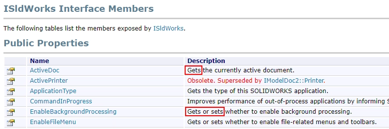
The object also has loads of properties and methods. You can find a list of properties and methods when you open the documentation for an interface, like ISldWorks, and at the bottom, click ISldWorks members.

A property is something that the object has, it does not have to be calculated. A property has a value that you can get and often you can also set it. You can find it all in the documentation:
When you call a method, you perform some action to extract, convert or change data. A method you will often use is ActivateDoc3, which activates a loaded model by its name.

1.2. Parameters and arguments
A method (often called a function) can have parameters, also called arguments (technically those are two different things, I know). When you call a method, you need to pass along those arguments. ActivateDoc3 has four parameters:

To activate a document (in VBA) called “Part1”, you can write the following:
1 2 3 4 5 6 | dim swApp as SldWorks.SldWorks set swApp = Application.SldWorks dim swModel as ModelDoc2 dim errors as Long set swModel = swApp.ActivateDoc3("Part1", true, swRebuildOnActivation_e.swUserDecision, errors) |
If the call succeeds, swModel now holds the active model object that I’ll explain below. If it fails, swModel stays nothing/null and the errors variable will explain why it failed.
This errors variable is an output parameter (ByRef in VBA, out in C#), which means the method can change this value. It lets you return multiple variables from a method. You can also use out variables in your own code, although it is generally frowned upon.
2. The ModelDoc2 object
The ModelDoc2 object (interface docs / members) is the second-most important object of the API basics and the Object Model. It has a two in it because it’s the second version of this object. The first version is deprecated and you should not use it anymore.
It holds information about a model. This can be a model that has its own file or it can be the model that belongs to an assembly component, but more on that later.
There are three document types:
- Parts
- Assemblies
- Drawings (which are also secretly assemblies)
You can access the current model via the swApp.ActiveDoc property (which is in the list of accessors for IModelDoc2) and once you have the model object, you can determine its type via the ModelDoc2.GetType method.
2.1. Casting the ModelDoc2 to a part, assembly or drawing
Once you know the model type, you can cast the object to the specific part, assy or drawing object. In VBA, these casts can be implicit, which can be both user-friendly and confusing:
1 2 3 4 | dim swModel as ModelDoc2 set swModel = swApp.ActiveDoc dim swPart as PartDoc set swPart = swModel 'This will fail if the model is not a part |
In C#, you need an explicit cast, which is the object type in brackets:
1 2 | ModelDoc2 swModel = swApp.ActiveDoc; PartDoc swPart = (PartDoc) swModel; |
Casting one SOLIDWORKS object to another type only works for very specific types, which I found highly confusing in the past. It is documented here, but not at many other places.
Interfaces that support casting are:
- IModelDoc2
- IEntity
- ITableAnnotation
- IFeature
- ISketchSegment
- IPropertyManagerPageControl
2.2. Casting a specific model back to its parent type
Once you have cast a ModelDoc2 to a part, assembly or drawing, you can access all properties and methods that are available for that specific model type. You can get all components from an AssemblyDoc object, for example.
But you can also cast an object back to its parent type. You’ll lose the model-specific members but you’ll gain access to the parent members again. The same holds for Features and the other types mentioned above.
3. IModelDocExtension
The IModelDoc2 interface has over 700 members, which is probably why SOLIDWORKS decided to add an extension object with 300+ members.
I haven’t found any real logic in the separation and the docs don’t mention it either. So I guess the advice is: if you can’t find a model property or method in IModelDoc2, check IModelDocExtension.
4. Parts – IPartDoc
Parts are the building blocks of any design. You use them to create geometry and volumes, whereas assemblies only use existing geometry (or subtract volume with assembly-level cuts). Parts consist of bodies and each body can have a material.
4.1. Feature and the FeatureManager / feature tree
You create a part by creating geometry, for example via an extrude. A feature might require other features to exist first, an extrude needs a sketch feature. So, to build your very first geometry:
- Have an empty part open
- Call InsertSketch
- Draw sketch entities, for example a circle
- Call InsertSketch again to close the sketch (very confusing, I know)
- Select the sketch via SelectByID2.
- Pass the sketch name, “SKETCH” as a type, zero as the position and null as the callout argument.
- You may need to use a mark when selecting multiple entities so that SOLIDWORKS knows which item is which. You can compare these marks to the different selection boxes (start face, end face, direction, etc) when you create a feature via the user interface. The docs for the feature you want to create will tell you which mark to use.
- Call FeatureExtrusion3 to create an Extrude feature.
- The methods to create features have highly inconsistent names, some start with Create, some with Feature, some with Insert.
- Some of these methods have 20+ parameters, which is insane. If you pass one incorrect parameter, it might not create the feature and the method returns null. Creating features therefore can be very frustrating, even for me.
- Luckily, SOLIDWORKS now lets you create a feature definition first, then create the feature from that definition. They are adding support for more feature types every year.
The next post in this series is dedicated to features: How to work with Features in the SOLIDWORKS API.
4.2. Getting and setting materials
You can assign a material to a part and/or to a body.
To get the material name, you could use MaterialIdName, but that property returns three values, separated by a pipe (example: “My MATERIALS|1.0038 (S235JR)|277”), which is not intuitive. I don’t even know what the third value is for.
It is easier to use GetMaterialPropertyName2 to get the name of the material and the name of the database the material belongs to. To set the material, call SetMaterialPropertyName2. To remove the material, pass an empty string for the material name.
4.3. How to work with sheet metal
To determine if a part is a sheet metal part, you can either check GetBendState or check if IsSheetMetal returns true for at least one body.
If a part is made from sheet metal, it has at least two configurations, a folded state and a flattened state. Each sheet metal body has its own flat pattern configuration. The flattened state really is a configuration with a few extra unsuppressed Flatten features, so be careful not to mess with these features.
You’ll find these flat pattern features at the bottom of the feature tree and you can access that folder via GetFlatPatternFolder. Every flat pattern also has a sketch with bend lines and a sketch with a rectangular bounding box.

To create a flat pattern in a DXF or DWG, call ExportToDwg2. This method quietly creates a drawing in the background, exports it, then closes it unsaved.
4.4. Working with weldments
Weldments are a great way to quickly build frames from standard profiles. In SOLIDWORKS, you create a multibody weldment in a single part. You can even add sheet metal bodies and normal bodies.
A weldment consists of four parts:
- A profile shape, selected at the top of the image below.
- One or more sketch lines for the path.
- A group of sketch segments with similar settings. You can add multiple groups in a single weldment feature.
- Group settings, like the angle and the point in the profile that is linked to the path.

When you are traversing the feature tree and GetTypeName2 for a feature returns “WeldmentFeature”, you can use GetDefinition to get the underlying definition in the form of IStructuralMemberFeatureData. From that definition, you can get the array of groups and for each group, you can get or set properties like the angle, alignment and the sketch segments that make up this group.
I use these properties to do magic in Drew, our drawing automation add-in that creates a sheet per unique weldment body with just one click.
4.5. Understanding cut list folders
SOLIDWORKS groups identical bodies in cut list folders and sheet metal folders get their own icon. To get the top-level folder, traverse the feature tree until you find a feature with the type name “SolidBodyFolder”, then get the BodyFolder via GetSpecificFeature2. The subfeatures of that solid body folder are cut list folders. Each folder can have bodies, but be aware, there are usually multiple folders that contain zero bodies.
In the image below, you see three types of folders:
- Sheet metal folder
- Solid body folder
- Weldment folder

There is a second way to get all cut list folders because each cut list folder also appears in the feature tree directly. So you can traverse the tree and add each feature whose type name is “CutListFolder” to a list. This method works better when the part has sub-weldments.
4.6. Sub-weldments
Users can create sub-weldments to group bodies that belong together, for example because they are assembled in a single step. Sub-weldments also appear as a folder in the cut list, but they are a pain to work with in the API.
4.7. How to build your own geometry
Let me start with a warning, building geometry from scratch is hard and it’s poorly documented. Even drawing a single straight line took me a few hours to figure out.
The basic steps to create a temporary body are:
- Get the Modeler.
- Create an infinite line (which is a curve) from a starting point and a direction.
- Call CreateTrimmedCurve2 to trim that line at the start and end.
- Create a wire body from one or multiple curves.
- Call Display3 on that body to display it.
- The color argument takes a single integer. More on that in the next section.
To create a hole or a cut-extrude, you first have to create a temporary body, then subtract that body from the main body. These operations are called boolean operations. The SOLIDWORKS developers also use these methods above to create geometry.
4.8. Colors as a single integer – COLORREF
For some operations, like displaying a temporary body, you have to pass a single integer for the color. This is an old Windows method and you can find more info here.
You can create your own color from RGB values in two similar ways:
- Calculate R*255^0 + G*255^1 + B*255^2.
- With bit shifts: R + (G << 8) + (B << 16).
Ditch the Toolbox, once and for all
Start using the fastener library that actually follows the standards
- No more mate errors
- Made for speed
- No yearly license fees
5. Assemblies – IAssemblyDoc and IComponent2
Where parts build geometry from scratch, assemblies only use existing part geometry. An assembly can take away volume though, in the form of cut extrudes and holes.
Assemblies basically define relations between parts and other subassemblies. In the API, these objects are called components and the interface is IComponent2.
A component can be a part or assembly. If you insert a part into an assembly twice, each instance has its own unique component object and the Name property contains the parent name(s) and the instance number. The part below would have the name “Main assembly-1/Subassembly-1/Part-1”.

5.1. Start at the root component
The top-level assembly is called the root component. Confusingly, you don’t get the root component from the ModelDoc2, not from the AssemblyDoc but from the active configuration object.
1 2 3 | var swApp = (SldWorks) Marshal.GetActiveObject("SldWorks.Application"); var swModel = swApp.ActiveDoc; var rootComponent = swModel.ConfigurationManager.ActiveConfiguration().GetRootComponent3(); |
Once you have the root component, you can get an array with its direct children with the GetChildren method. The order of the children is random.
If the child component is an assembly (and you have verified this, see next section), you can get the children of that subassembly recursively.
5.2. How to add a component to an assembly
It seems so simple, just call AddComponent5 and pass the component path as an argument. But that only works if you have loaded the model, either in the background or as part of an assembly.
To load a model in the background, then add it to the assembly:
- Call DocumentVisible to mark the next models as invisible so they are not opened in their own window.
- Call OpenDoc6 or OpenDoc7.
- Call DocumentVisible again to reset the setting.
- Call AddComponent5 to add the new model to the assembly
5.3. Get the ModelDoc2 from Component2 (+ how to fix the ModelDoc2 being null)
Every component has an underlying ModelDoc2 component, which can be an AssemblyDoc or PartDoc object. You get it by calling the GetModelDoc2 method. But be aware, this method can also return null if the model is not fully loaded.
How can that be, you ask? Well, you may know that you can load an assembly faster by loading it in Large Design Review mode or Lightweight mode. Large Design Review only loads the assembly file itself, no references, while Lightweight only loads about half of all data from the underlying parts and subassemblies. Resolved mode loads everything. To learn more about the underlying technology for these open modes, check out my ebook Secrets to SOLIDWORKS performance.
So if you loaded an assembly in Lightweight mode, some parts or subassemblies may not be fully loaded. That’s when GetModelDoc2 will return null. You can fix this by calling ResolveAllLightweightComponents before you need the models. Resolving the components can take a few seconds to a few minutes.
5.4. Component transforms
Each component has a position and an orientation in assembly space. SOLIDWORKS uses 4×4 matrices for these orientations and they call them MathTransforms.
To learn more about these confusing objects, check out A complete overview of matrix transformations, a blog post I really needed when I started with matrix transformations.
5.5. Watch out for SpeedPak configurations
If the active configuration is a SpeedPak configuration, many API methods will not return anything. You can check this with the IsSpeedPak property on a configuration or component.
6. Drawings – IDrawingDoc
Drawing automation is my cup of tea since I worked on Drew for thousands of hours. These are the basics:
6.1. A drawing is secretly an assembly
I found a dozen hints that drawings are secretly assemblies. Think of it, they contain multiple copies of existing geometry. You can create cuts in the form of section views and you can still rotate the views in 3D. Just like assemblies. The sheet is just another assembly component.
6.2. Sheets
Every drawing has at least one sheet. Even if you delete the active sheet, SOLIDWORKS adds a new one.
You can get the active sheet or get a sheet object by its name. Since you’ll often need to use the sheet name, you’ll also need the GetSheetNames method.
Because sheets can also contain notes and blocks, just like views, the first view on the sheet is actually the sheet. When you call IView.GetNextView, the next one is a real view (or null if there are no views).
6.3. How to change the sheet format
To set the sheet format on a new, blank sheet, call SetProperties2, then call SetTemplateName, in that order. Annoyingly, even the SOLIDWORKS developers could not agree on what to call a template and what to call a sheet format.
To change the sheet format of an existing sheet, call IDrawingDoc.SetupSheet6. It needs way too many arguments, but you can get most of them from the current sheet. You can usually leave PropertyViewName empty, but make sure to set RemoveModifiedNotes to true to delete the old sheet format. The zones and zone margins are hardly used, so I use default values for a 5×5 grid and 10mm margins.
6.4. Views
A view is a projection of a certain configuration of your model from a certain angle (see the similarities with assemblies again?).
It has a position on the sheet, but that view center is not the same as the model origin. It’s just a random point, roughly in the center of the view. Each view has a ModelToViewTransform property.
Each view has a type. The first view is usually a named view and dependent views are called projected views. Projected views have no reference model, so you may need to get the parent view first.
A view contains edges, which are edges that are also in the model, and silhouette edges, which are just projections and have no edges in the model.
Where assemblies contain components, views contain drawing components and you get the root component via the RootDrawingComponent property. From the root component, you can get its children or its corresponding assembly component. You don’t need these very often, but it’s good to be aware of their existence.
To delete a view, select it by its name, then call EditDelete.
6.5. Sketches in a view
Each view (and the sheet as a view) has its own sketch that you can get via GetSketch. If you want to add notes to this view and you want them to move with the view, you need to add them to this sketch.
To be able to add notes and blocks to a view (or to the sheet as a view), you need to activate the view first.
This sketch has its own matrix transformation ModelToSketchTransform, which you need to convert items within a view back to model space. I talk about it in my blog post on matrix transformations.
6.6. Get all lines in a view – view data
Many of the methods in the IView interface are for getting the visible lines and other entities in the view. I mostly use these two:
- GetVisibleEntities2:
- Takes the component and entity type as arguments. If a view has multiple components, you may need to call GetVisibleComponents first and iterate over the components.
- Returns an array of entities or silhouette edges.
- Be aware, getting a list of silhouette edges takes about one second per edge. And since you have no idea how many edges there will be (calling a method to get the count takes just as long), this can take really long for a large assembly or complex part.
- GetPolylines6:
- GetPolylines7 exists but it is often slower, so I use version six.
- This method returns a terribly long array of doubles and you need a terribly complex method to translate these doubles back to doubles, integers, booleans, colors, line thicknesses and 3D points. So please make sure to create unit tests for your translator functions.
- There may also be many zeroes at the end of this array, which are not documented. Luckily, you can delete and ignore them.
- The second double value for each line is called GeomDataSize and its value is often zero or 12. If it is 17, treat it as zero because, somehow, there will be 17 zeroes at the end of the array.
6.7. BOM tables and features
A bill of materials needs to be attached to a view and you call InsertBomTable4 to add one. But to get an existing BOM, you get the first sheet as a view via GetFirstView, then get the tables attached to that view via GetTableAnnotations. That might be because a Bill of Materials is not under a sheet or view in the feature tree, it is on the same level as sheets:

If you traverse the feature tree, you will find a feature with the type name “BomFeat”. Use GetSpecificFeature to get the underlying BomFeature or call GetFeature to get back the feature.
The BOM feature has one or more bom table annotations that you get via GetTableAnnotations, which are specialized table annotations. You use the specialized version to get bom-specific properties and cast it back to a table annotation to get generic properties.
Be aware that table annotations may return identical or overlapping data.
Also: getting the item number can be really confusing. I use GetComponentsCount2, where one of the out parameters is the item number.
All blog posts in this series
- The SOLIDWORKS Object Model + API explained
- SOLIDWORKS API: the basics - SldWorks, ModelDoc2
- How to work with Features
- Persistent ID and sketch segment ID and more
- All identifiers in the SOLIDWORKS API
- About return values
- Entities and GetCorresponding
- How to work with selections
- How to use custom properties
- Understanding math, MathVector and MathTransform
- Toolbars, menus and the Command Manager
- How to create task panes and Property Manager Pages
- How to create your own SOLIDWORKS add-in
- Creating add-ins with SolidDNA: the basics