Understanding math and MathTransform in the SOLIDWORKS API (part 10)
This is part ten in our blog series about the SOLIDWORKS API. Links to all other parts are available at the bottom of this post.
This blog post dives into math and transformation matrices: the heart of SOLIDWORKS models and drawings.
In this blog post, you’ll find
- Everything is a matrix
- SOLIDWORKS and its geometric objects
- IMathUtiltity: create vectors and matrices
- IMathPoint
- IMathVector
- IMathTransform: more than a rotation matrix
- Model views
- Coordinate systems
- Planes
- Sketches
- Blocks
- Bodies
- Components
- Patterns
- Drawing views
1. Everything is a matrix
Every point, line, sketch and component in SOLIDWORKS uses math, vectors and matrices. So if you are a developer who hasn’t learned about matrices in school, it’s time to dig in.
To give you a hint of what’s about to come:
- A point and a vector have three coordinates: X, Y and Z.
- A sketch and a drawing view have their own coordinate system.
- You need matrix calculations to go between coordinate systems.
- Each assembly component has a MathTransform that defines its position and orientation.
I have explained what a matrix is and the basics of matrix math in A complete overview of matrix transformations in the SOLIDWORKS API, so I will not repeat myself here. Please read that post first if you’re new to matrix math, I have just refreshed its contents.

And while that post is a great starting point for matrix math and the API, it isn’t very structured. So I’m taking a more methodical approach this time.
2. SOLIDWORKS and its geometric objects
Every API that deals with math has points (2D and 3D), vectors, matrices and methods to multiply those. SOLIDWORKS is no different. Instead of taking on external dependencies, they created their own point, vector and matrix (well, matrix transformation) objects.
Most SOLIDWORKS objects that are controlled by math will return these Math objects or need them as inputs. Most APIs that use a point, however, have separate X, Y and Z parameters or an array of three doubles.
Math objects and performance: A premature warning
Within my own software, I prefer to use System.Windows.Media.Media3D.Point3D because it’s bundled with the .NET Framework and it’s way faster than its SOLIDWORKS equivalents. So if I have to perform math, I convert a MathPoint to a Point3D as soon as possible, do my magic, then convert the result back to a MathPoint as late as possible.
You will generally not notice the speed difference, so go ahead and use the SOLIDWORKS objects.
3. IMathUtiltity: create vectors and matrices
If you want to create a new MathPoint, MathVector or MathTransform object, you need to get the IMathUtility object first. To get it, you call ISldWorks.IGetMathUtility. You can also call GetMathUtility (without the I at the start), but then you have to cast the object to a MathUtility object yourself. Strange, I know.
In practice, you rarely create your own math objects. You mostly get them from APIs and pass them to other APIs. But when you eventually do, you know what to do.
4. IMathPoint
The most basic of all geometry, the humble point. There is no 2D point in SOLIDWORKS, only a 3D point.
If you view the interface page for IMathPoint, you can see all 30 methods and properties that return a MathPoint. We call those Accessors. To learn how to read the SOLIDWORKS documentation, check out part one of this blog series: The SOLIDWORKS Object Model + API explained.
I would expect this object to have X, Y and Z properties, but it doesn’t have those. Instead, it only has the ArrayData property, which returns an array of three doubles. Maybe to prevent you from only changing one of those values? The ArrayData property has a setter, so you can change the point without having to create a new object.
It also has methods to translate a point by adding a vector, to multiply/scale it, to transform the point and to get the difference between two points as a vector.
5. IMathVector
One step above points, we have vectors. Just as with points, there is only a 3D vector in the SOLIDWORKS API and no 2D vector.
A vector represents a movement, a change in location, a difference between two points. And while it also has three coordinates (and thus an ArrayData property), it’s different from a point: a vector has a length.
You can multiply two vectors in two ways: the cross product (which returns another vector) or the dot product (which returns a single number). To learn more, check out the Wikipedia pages on the cross product and the dot product.
Of course, we also have a method to normalise (British spelling) a vector, which returns a vector of length 1 or to multiply a vector by a matrix.
6. IMathTransform: more than a rotation matrix
Most matrix math in 3D space revolves (pun intended) around points (1×1), vectors (3×1) and matrices (3×3):
- To scale a point or a vector, you multiply it by a number.
- To move (=translate) a point or vector, you add a vector to it.
- To rotate a vector, you multiply it by a matrix.
- You multiply two matrices to create the combined rotation.
A math transform is a smart way to have a single 4×4 matrix that contains both a rotation, a translation and a scale.
Not used means these values are always zero. I remember that n, o and p are zero because together, the form NOP, an old code instruction that tells the computer to do nothing 😄
SOLIDWORKS did not invent this matrix; the same matrix structure is used in Microsoft .NET Matrix3D for 3D graphics.
Note that SOLIDWORKS names the elements per submatrix. It always uses this custom order, for example, when it returns 16 elements as ArrayData:
- 0-8 / a-i / rotation submatrix
- 9-11 / j-l / translation vector
- 12 / m / scaling factor
- 13-15 / n-p / not used
The first row of the rotation submatrix is called the ‘x-axis component’ of the rotation. When you call the GetData method, SOLIDWORKS returns the five objects that make up the matrix:
- The X-axis component (in the form of a MathVector)
- The Y-axis component (MathVector)
- The Z-axis component (MathVector)
- The translation vector (MathVector)
- The scale (double)
Other methods that you will use often are IMultiply and IInverse. Both return the resulting matrix.
Let’s do something useful with matrices
Now that we have handled the basics, let’s apply this knowledge in SOLIDWORKS. We dive into how to rotate your active view and how to work with sketches, planes, assembly components and drawing views.
7. Model views
Here we have one of our fasteners, an ISO 14579 bolt, and we look at it from an isometric view. Every time you rotate your model, SOLIDWORKS updates the ModelView object of the active model.
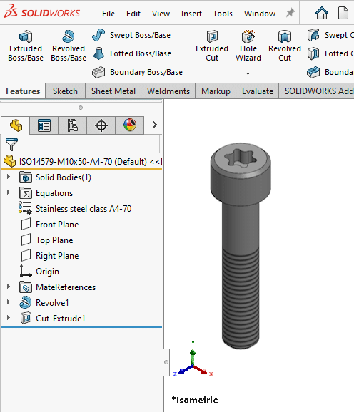
Let’s see how we get that model view matrix in VBA:
1 2 3 4 5 6 7 8 9 10 11 12 13 14 15 16 | Option Explicit Sub main() Dim swApp As SldWorks.SldWorks, swModel As ModelDoc2, swModelView As ModelView Set swApp = Application.SldWorks Set swModel = swApp.ActiveDoc Set swModelView = swModel.ActiveView Dim transform As MathTransform, arrayData As Variant Set transform = swModelView.transform arrayData = transform.arrayData Debug.Print Round(arrayData(0), 3) & " " & Round(arrayData(1), 3) & " " & Round(arrayData(2), 3) Debug.Print Round(arrayData(3), 3) & " " & Round(arrayData(4), 3) & " " & Round(arrayData(5), 3) Debug.Print Round(arrayData(6), 3) & " " & Round(arrayData(7), 3) & " " & Round(arrayData(8), 3) End Sub |
This prints the following rotation matrix:
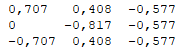
You may recognize these values from high school math:
- 0.707 = 0.5 * sqrt(2) = 1/sqrt(2)
- 0.577 = 1/sqrt(3)
- 0.408 = 1/sqrt(6)
Set the orientation of the current model
If you want to change the orientation of your current model, you cannot set the complete MathTransform matrix directly. But you can set the Orientation, Translation and Scale properties separately.
The IModelView interface has many other properties and methods for manipulating your current model window. It controls the display mode, camera, zebra stripes and I’ve used GetMouse once for a nice hack. You may also need to call GraphicsRedraw if SOLIDWORKS consistently forgets to update the window after running your code.
Standard orientations
SOLIDWORKS shows the orientation of your current model in the bottom left. If you want to recreate one of the standard views, you can use these rotation matrices:
![]()
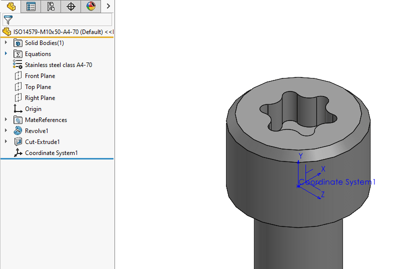
8. Coordinate systems
Every model has an origin and a coordinate system. It defines the X-direction, Y-direction and Z-direction, all perpendicular to the other ones. You can view your current model orientation using the coordinate system indicator in the image above.
You cannot delete the default coordinate system and it’s not present in the feature tree, not even as a hidden feature.
But a model can have multiple coordinate systems. Just call FeatureManager.CreateCoordinateSystem to create a new coordinate system feature. You need to pass a compatible set of geometries as parameters, or I bet SOLIDWORKS will return null instead of a new feature. Debugging issues like that is always a pain, so I manually try to create such a coordinate system from the source geometry before trying to automate it.
Ditch the Toolbox, once and for all
Start using the fastener library that actually follows the standards
- No more mate errors
- Made for speed
- No yearly license fees
9. Planes
Planes, or reference planes, basically create geometry without creating a face. In the SOLIDWORKS API, you access them through the IRefPlane interface.
Reference planes have an orientation based on one or more references. They have very few properties in the API: they have a BoundingBox property, you can get (but not set) the corner points and you can get the transformation matrix.
I think that you cannot set the orientation because a reference plane is based on its references; update those and the plane moves along with them.
If you want to modify the plane or its references, you need the feature object first, then call GetDefinition to get the underlying IRefPlaneFeatureData object. Once you have the feature data:
- Call AccessSelections
- Make your changes
- Call Feature.ModifyDefinition to save your changes
- Or call ReleaseSelectionAccess to discard your changes
This method is the same for every feature definition that requires geometry selection(s) as input.
10. Sketches
A normal 2D sketch only uses 2D points. So when you call SketchManager.CreatePoint, the Z-argument is ignored.
Sketches on standard planes
If you create a sketch on a standard plane, the sketch origin coincides with the model origin. But a sketch feature has its own coordinate system with its own axes, so the X-axis in the sketch may coincide with the negative Y-axis of the model. You can create a sketch on any face or plane, and also on the back side of the plane.
To get the MathTransform of a sketch, you get the ModelToSketchTransform property. As the name suggests, this matrix represents the transformation from the main model to the sketch. To go from sketch space to model space, you need to multiply your sketch point coordinates by the inverse of this transformation matrix.
Sketches on faces and custom planes
If you don’t create a sketch on a standard plane, but on a model face or a custom plane, the sketch origin can be anywhere. I have found no rhyme or reason for the position of the origin and you cannot choose the position of the origin. The ModelToSketchTransform property is get-only, so you cannot change the orientation of the sketch just by updating this matrix. You can only edit a sketch definition by changing the face it sits on.
11. Blocks
A sketch block is a group of sketch geometries that you can use over and over. You select a couple of sketch segments, turn them into a block and insert that block multiple times. You can save the block to a file (but it’s not mandatory) so you can use it in other models/drawings as well.
In the API, we have block definitions (ISketchBlockDefinition) and block instances (ISketchBlockInstance). Do not use IBlockDefinition and IBlockInstance, those are old interfaces that have been replaced 15+ years ago.
Block definition
You first create or add a block definition, let’s say, to a drawing. This is the master object; it controls the content of the block instances. Change the definition to change all instances.
When you create or add a definition, SOLIDWORKS also creates the first instance. This happens both in the user interface and with the API. After that, you can add instances directly.
A block definition has no position because it’s not added to the drawing sheet. But it does have an underlying sketch that you can access via GetSketch. And that sketch does have a matrix transformation.
Block instance
A block instance is a child object of the block definition parent. You add instances to your drawing sheet, so the object does have an InstancePosition property.
But that position really is a part of a matrix, which you can access directly via the BlockToSketchTransform property of a block instance. This matrix helps you “to transform coordinates from the sketch block space to the host sketch space”, according to the docs. The host sketch space could be the sketch in your part, or the underlying sketch of a drawing view or the sheet itself. We’ll talk about drawing views later on. Managing transformations in drawing views is a pain, believe me I know, because you need to manage the transformations of the view, of the block definition and of the block instance. And you cannot mix up the order of the matrix multiplication, even though the API docs will never tell you how to do it properly.
You cannot set the BlockToSketchTransform property directly, but you can set the position, scale and angle.
12. Bodies
You build bodies in parts by creating geometry, so an IBody2 object has no transformation matrix object. It does have an ApplyTransform method, which lets you move temporary bodies, I think.
There is also the GetCoincidenceTransform2 method, which lets you calculate the matrix transformation between two identical bodies.
13. Components
A component is a copy of a part or assembly, put into another assembly. That means it has a position, orientation and therefore a Transform property.
Adding components
When you add a single component to an assembly, you can only specify the position, not the orientation. As we noticed before, SOLIDWORKS does not use a MathPoint parameter here, but X, Y and Z parameters.
When you add multiple components, you do get the option of passing the orientation of each component. But you have to create a single array with 16 values for each component:
Transforms contains an array of [(Names count) x 16] doubles. This parameter stores one transformation matrix of 16 doubles for each component in Names. If a component’s transformation matrix is null, then the component is placed in the assembly such that the component’s user-defined coordinate system coincides exactly with the default coordinate system of the assembly (no transformation). See IMathTransform for details about transformation matrices.
You can also pass an array of coordinate systems, but I’m not 100% sure how that works.
Creating a temporary component copy
SOLIDWORKS has a built-in feature to display changes to component positions, which they use when you create patterns or exploded views. They call the underlying transformation matrix the PresentationTransform. If you enable AssemblyDoc.EnablePresentation, then give this property a value, it shows the component at a new position without really moving it or changing mates. Make sure to call RemovePresentationTransform to reset a component, or to set EnablePresentation to false to reset all components, after you’re done.
14. Patterns
We have three types of patterns: sketch patterns (inside a sketch), geometry patterns (in parts) and component patterns (in assemblies).
Sketch patterns
I’ve been looking into patterns in sketching and concluded that you don’t want to manage these patterns with the API. There are no interfaces to manage these patterns, which makes it hard to reference them and to find them later.
For example, you create a linear pattern in a sketch by calling SketchManager.CreateLinearSketchStepAndRepeat and passing 13 parameters, most of which are simple doubles. Since there is no object to return, it only returns a boolean to tell you whether the API call succeeded, yay. Editing patterns is even harder because there is no way to get or select an existing pattern, you have to find the seed sketch segment, select it and call the edit method.
Geometry patterns
Because I always get confused about which objects are geometry patterns and which are component patterns, I’ve made two lists. (And while I created those lists, I got them confused again 😬) These are seven geometry patterns and their feature data objects:
- Circular pattern
- Curve-driven pattern
- Fill pattern
- Linear pattern
- Mirror pattern
- Sketch pattern
- Table pattern
Most of these interfaces have a GetTransform method. Pass the instance number of the component as a parameter and SOLIDWORKS will tell you the transformation matrix for that component. I’m not a big fan of using instance numbers since they don’t have any real meaning, but at least you can write a foreach loop to get the component orientations.
Fill pattern and mirror pattern objects don’t have a GetTransform method; I don’t know why.
Component patterns
There are seven types of component patterns in assemblies. Most of their interfaces have the prefix “local”, but not all. The word local also doesn’t help me remember it. These are their feature data objects:
- Chain component pattern
- Circular component pattern
- Curve-driven component pattern
- Linear component pattern
- Pattern-driven / derived component pattern
- Mirror components
- Sketch-driven component pattern
And just as with the geometry patterns, most of these have a GetTransform method. Since most patterns are derived from other geometry, like a rotation axis for circular patterns, you cannot set the transformation matrix of a component directly.
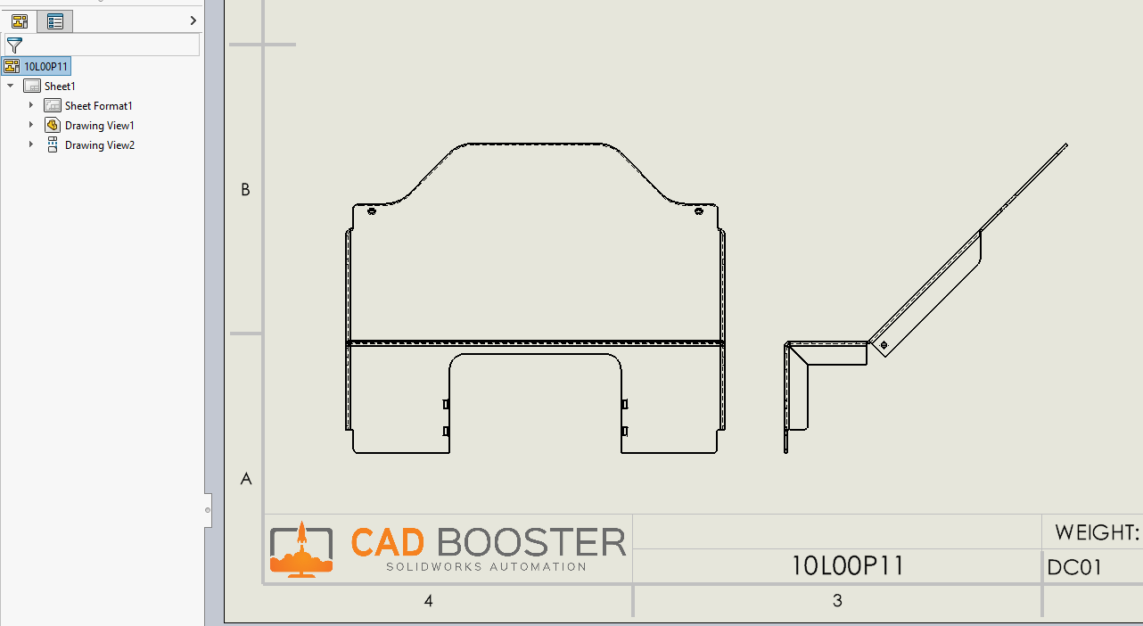
15. Drawing views
We have been working our way up from sketches in parts, to assemblies, to end up at drawings (which are also secretly assemblies). Drawing views are the most challenging to work with regarding transformations because you have to combine transformation matrices. A few top-level highlights:
- Every drawing view has a position (ok, that one may be straightforward)
- The model in that drawing view has an orientation
- The origin of the model is not the same as the position of the view
- Every drawing view has a sketch that you can add dimensions and blocks to. This sketch stays parallel to the sheet, even when you change the view.
- The drawing sheet is also a view
Drawing sheets
Every drawing sheet has its origin in the bottom left. Objects on the sheet have three coordinates, so you can ignore the Z-coordinate. The Z-coordinate is not always zero, strangely enough.
As and I said before, every view has a sketch that you can add notes and dimensions to. The sheet also has such a sketch and fortunately, their origins coincide.
The only thing that you have to take into account regarding math and transformations is the sheet scale.
Drawing views
A view is a copy of a part or assembly, shown in front of a sheet object. The view has a scale (which could be the same as the sheet scale) and the model has an orientation.
The transformation matrix to go from model space to view space is called ModelToViewTransform, but you can also call GetViewXform to get the 12 useful double values from that matrix directly. I don’t know why GetViewXform exists, I think it’s an old API that they have never deprecated.
This model to view transform does not take the position of the view into account. You can also call GetXform to get the X- and Y-coordinates of the position, plus the scale.
As I said before, the origin of the view is not identical to the origin of the model in the view. The origin of the view is a random point, roughly in the center of the view.
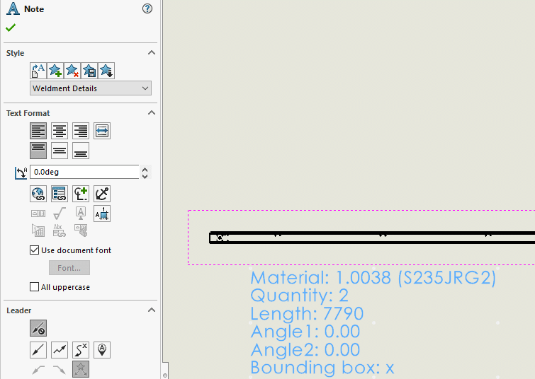
Blocks
We have already discussed blocks before, so I won’t repeat that information. But working with blocks in drawing views is a different beast. A few highlights:
- A block instance has a position, angle and scale.
- A block instance has an underlying sketch. Use BlockToSketchTransform to transform coordinates from the sketch block space to the host sketch space.
- Changing the view scale does not change the block scale. However, the block scale in the transformation matrix is the result of dividing the block scale by the view scale. So my guess is that SOLIDWORKS also changes the block scale when you change the view to make it look like the block hasn’t changed.
- This transformation matrix stays the same when you move the view, but it does change when you move the block inside the view.
Working with block instances remains tricky, I still haven’t reached the point that I fully understand their transformations.
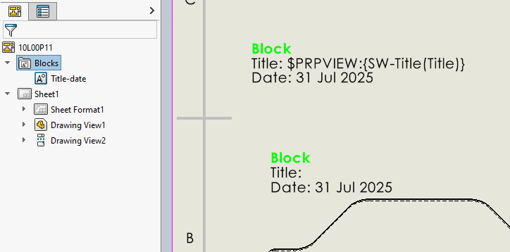
A block with a definition in the feature tree and two instances, one of which is linked to a view as its data source.
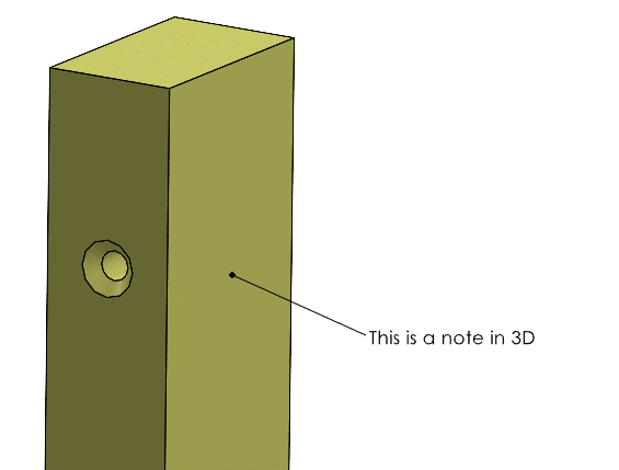
Notes
Notes are a little simpler than blocks. You usually see them as a piece of text or as a BOM balloon. To get or set their position, you need to get the underlying annotation via GetAnnotation first, then call GetPosition or SetPosition2.
To change the angle, you can access the Angle property on the note directly.
The underlying annotation has a GetPlane method that returns the rotation matrix, so not the whole transform, as an array of nine doubles. It’s not very useful for notes in a drawing because it will always return the identity matrix. But when you add notes to a part, this matrix will tell you the note’s orientation.
The annotation interface also has a GetFlipPlaneTransform method and this method does return a MathTransform, but I’ve only ever seen it return the identity matrix. So it doesn’t seem to do anything useful.
Final words
I hope this long list of MathTransform objects has been useful to you; it was certainly interesting to me to write with such a systematic approach.
If anything is missing or incorrect, please get in touch and we’ll fix it.
If you want to learn more about the SOLIDWORKS API, check out the other posts in this series below.
All blog posts in this series
- The SOLIDWORKS Object Model + API explained
- SOLIDWORKS API: the basics - SldWorks, ModelDoc2
- How to work with Features
- Persistent ID and sketch segment ID and more
- All identifiers in the SOLIDWORKS API
- About return values
- Entities and GetCorresponding
- How to work with selections
- How to use custom properties
- Understanding math and MathTransform
- Toolbars, menus and the Command Manager
- How to create task panes and Property Manager Pages
- How to develop a SOLIDWORKS add-in
- SolidDNA: a better framework for SOLIDWORKS add-ins